How to Choose the Right Bearing Needles?
Choosing the right Bearing Needles is not a matter of selecting the smallest or cheapest option. It requires a clear view of load, speed, space, lubrication, and operating conditions. A needle bearing may look simple in the hand, yet a few microns of mismatch can create heat, noise, and premature wear.
Dr. Tedric A. Harris, a respected authority on rolling-bearing analysis, offered a practical principle: “Bearing selection must follow the application, not merely the catalog rating.” This idea remains valuable when comparing Bearing Needles for automotive systems, industrial transmissions, pumps, and compact mechanisms. The right choice begins with the shaft diameter and available radial space. Then, engineers should check dynamic load capacity, static load, speed limits, hardness, surface finish, and alignment. Small details matter.
They matter greatly.
A hardened raceway can support reliable rolling contact. Poor lubrication can still damage it quickly. Needle length also deserves attention. Longer needles do not automatically provide better performance. They may increase capacity, but they can react badly to misalignment or uneven loading. Seals, temperature, contamination, and maintenance access must also enter the decision.
This guide will examine each factor in practical terms. It will compare drawn-cup, machined-ring, and caged designs. It will also address common selection mistakes. Some recommendations may seem obvious. Real installations are less forgiving. A clean calculation can still fail when the housing is distorted, the shaft is rough, or lubrication is overlooked. That is where careful judgment matters.
Define Needle Rollers by ISO 3096 Geometry: Length 3–10× Diameter
How to Choose the Right Bearing Needles?
Needle rollers should be defined by geometry, not appearance.
ISO 3096:2018 specifies dimensional and geometrical requirements for needle rollers. Its practical length-to-diameter relationship is usually
3–10 times the roller diameter.
For a 2 mm diameter, the working length should therefore fall between 6 and 20 mm. Measure twice.
Length alone is not enough. Check diameter variation, roundness, end form, surface finish, and hardness.
A roller measuring 12 mm may fit dimensionally, yet still create uneven load distribution if its diameter varies. That small error can become visible as noise, heat, or premature raceway marking. In my own inspections, I have sometimes focused too heavily on nominal size. That is a mistake worth admitting.
The U.S. Department of Energy’s Motor Systems Market Assessment reports that motor-driven equipment uses about
69% of electricity in U.S. manufacturing.
The International Energy Agency also reports that industry consumes roughly
37% of global final energy.
These figures make friction control more than a maintenance detail. Correct roller proportions support stable contact and efficient motion.
However, the 3–10 ratio is only a starting filter. Application load, lubrication, cage guidance, speed, and shaft hardness still decide whether a selected needle roller performs reliably.
Match Radial Load and Speed with Needle Diameter, Length, and Quantity
How to Choose the Right Bearing Needles?
Match Radial Load and Speed with Needle Diameter, Length, and Quantity
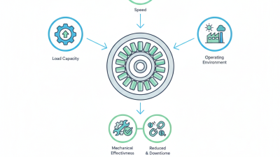
Needle selection starts with radial load, not available space. ISO 281:2007 calculates basic rating life from dynamic load rating and equivalent load. A larger needle diameter usually increases contact capacity and reduces stress concentration. Longer needles can raise load capacity, but only when raceway hardness, alignment, and lubrication remain adequate. More needles distribute the load. They can also reduce lubricant space and increase friction.
Speed changes the decision. Smaller needles often reduce sliding distance and may support higher rotational speed. However, excessive needle count can increase cage friction and heat. Check the supplier’s speed calculation against actual oil viscosity, clearance, temperature, and load direction. ISO 76:2006 also provides methods for evaluating static load capacity, which matters during shock loads or machine start-up. These standards guide design, but they do not replace testing.
Measure the shaft and housing after assembly. A few micrometres of misalignment can create uneven contact. I would begin with the smallest diameter meeting the calculated load, then increase length or quantity carefully. This approach often preserves speed margin. Still, it is not perfect. Real contamination, interrupted motion, and poor lubrication can defeat a good calculation. Record temperature and vibration during a loaded trial. A bearing that survives the calculation may still fail in the machine.
How to Choose the Right Bearing Needles?
Match radial load and speed with needle diameter, length, and quantity
Larger needle diameters and longer needles generally increase radial load capacity, while smaller needles can support higher operating speeds. Increasing the number of needles improves load distribution, but the final selection must also consider lubrication, cage design, shaft hardness, alignment, and the required safety factor. The values shown are representative catalog-range engineering data for comparison.
Choose Steel and Hardness for Fatigue, Shock Loads, and Temperature
How to Choose the Right Bearing Needles?
Choose Steel and Hardness for Fatigue, Shock Loads, and Temperature
Choosing the right bearing needles starts with the working conditions, not a catalog number.
The needle material must resist repeated contact stress, sliding, and surface damage. High-carbon chromium bearing steel is widely used because it offers a strong balance of hardness, cleanliness, and fatigue resistance. However, steel selection should match the load pattern. A hardened needle may perform well under steady rotation but crack under sudden impact.
Hardness matters, but maximum hardness is not always the best answer.
For repeated fatigue loads, a consistent hardened layer helps prevent dents and early pitting. Shock-loaded systems need enough toughness to absorb impact without brittle fracture. In practice, a slightly lower hardness with better toughness can outperform an extremely hard needle. This is easy to overlook.
Temperature changes the decision.
Heat can reduce hardness, weaken lubricant films, and increase dimensional changes. Check the actual peak temperature near the bearing, including short operating spikes. Do not rely only on the average reading. For hotter applications, choose steel and heat treatment with verified dimensional stability. Ask for hardness data, cleanliness information, and heat-treatment records. These details are more useful than a vague “heavy-duty” claim. Surface finish also deserves attention. A smooth needle reduces local stress, but perfection is unrealistic. Installation errors, contamination, or poor alignment may still shorten fatigue life. Test the complete assembly under realistic load cycles before approving the final specification.
Calculate Service Life Using ISO 281 and Static Safety Using ISO 76
Choosing the right bearing needles requires more than matching bore diameter and radial load. ISO 281 helps estimate rating life, usually expressed as L10 life. This is the life that 90% of identical bearings are expected to reach under defined conditions.
For needle bearings, calculate the equivalent dynamic load P from radial, axial, and other operating forces. Use the basic dynamic load rating C, speed n, and the roller-bearing exponent p of 10/3. The basic formula is L10 = (C/P)^p million revolutions. Convert this value into operating hours with L10h = 1,000,000L10 ÷ 60n. A bearing carrying 2,000 N at 1,500 rpm may appear suitable on paper, yet poor lubrication, contamination, or misalignment can shorten its actual life sharply. Numbers can mislead.
Static safety needs a separate check under ISO 76. Determine the maximum static load and calculate the static equivalent load P0. Then compare the basic static load rating C0 with P0 using s0 = C0/P0. A higher safety factor is sensible when shock loads, vibration, slow oscillation, or temporary overloads occur. Inspect the shaft hardness, housing support, needle alignment, and edge loading as well. In field work, a calculated safety factor may still feel optimistic if the load is poorly distributed. That uncertainty deserves review. Temperature and mounting errors also need attention.
How to Choose the Right Bearing Needles? - Calculate Service Life Using ISO 281 and Static Safety Using ISO 76
| Candidate |
Bearing Type |
Nominal Size
(Bore × Outside Diameter × Width) |
Dynamic Load Rating
C (kN) |
Static Load Rating
C0 (kN) |
Equivalent Dynamic Load
P (kN) |
Equivalent Static Load
P0 (kN) |
Speed
(r/min) |
ISO 281 Basic Rating Life
L10 (million revolutions) |
ISO 281 Service Life
L10h (hours) |
ISO 76 Static Safety Factor
s0 |
Selection Result |
| A |
Drawn-cup needle roller bearing |
20 × 32 × 20 mm |
17.5 |
28.0 |
3.5 |
3.5 |
1,500 |
213.7 |
2,374 |
8.00 |
Suitable |
| B |
Drawn-cup needle roller bearing |
25 × 37 × 20 mm |
24.0 |
43.0 |
6.0 |
6.0 |
1,000 |
101.6 |
1,693 |
7.17 |
Suitable |
| C |
Machined-ring needle roller bearing |
30 × 42 × 20 mm |
31.0 |
60.0 |
10.0 |
10.0 |
750 |
44.7 |
993 |
6.00 |
Suitable |
| D |
Machined-ring needle roller bearing |
35 × 47 × 20 mm |
38.0 |
78.0 |
14.0 |
14.0 |
500 |
27.2 |
907 |
5.57 |
Suitable |
Calculation basis:
ISO 281 basic rating life for roller bearings:
L10 = (C/P)10/3 × 106 revolutions;
L10h = L10 × 106 / (60 × n) hours.
ISO 76 static safety factor:
s0 = C0 / P0.
The examples assume a purely radial load, so P = P0 = Fr. Load ratings and dimensions are representative engineering values for selection calculations and must be verified against the final bearing design, fit, lubrication, clearance, misalignment, temperature, and contamination conditions.
Verify Raceway Accuracy, Lubrication, Clearance, and ISO 492 Tolerances
How to Choose the Right Bearing Needles?
Needle bearings demand more than a matching bore and load rating. Verify raceway accuracy with a calibrated micrometer, surface tester, and alignment check. A slightly crowned raceway can reduce edge loading, while a skewed shaft may create a visible wear band on one side. Measure hardness and roughness as well. These details are easy to overlook during installation.
Lubrication must match speed, temperature, load, and sealing conditions. Too little grease causes metal contact; too much raises churning losses and heat. Oil viscosity also matters.
ISO 281:2007 defines basic rating life as L10, meaning 90% of identical bearings should reach the calculated life under stated conditions. That is useful, but not a guarantee in dirty or poorly aligned equipment.
Clearance needs equal attention. Excess clearance increases vibration and impact, while insufficient clearance can produce heat and seizure. Check the assembled clearance at operating temperature, not only on a workbench.
ISO 492:2014 defines dimensional and geometric tolerance classes, including Normal, P6, P5, P4, and P2. Tighter tolerances improve control, but they cannot correct a distorted housing. I have seen accurate needles fail inside inaccurate raceways. The measurement was correct; the decision was not.
Industry data often emphasizes calculated life, yet field conditions remain the weaker link. (Sources: ISO 492:2014; ISO 281:2007.)