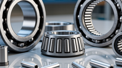
Choosing the right Needle Roller bearing in 2026 requires more than matching a bore diameter. Engineers must balance load, speed, lubrication, temperature, contamination, and available space. A bearing that fits the drawing can still fail early.
Industry data supports this careful approach. Fortune Business Insights, in its 2024 Ball and Roller Bearings Market report, identifies industrial automation, automotive systems, and renewable-energy equipment as major demand drivers. These applications increasingly require compact bearings with higher reliability and lower maintenance needs. The U.S. Department of Energy also links improved machine efficiency with effective component selection and preventive maintenance. Small losses matter.
Real-world experience adds another layer. A needle bearing inside a gearbox may face shock loads, misalignment, and limited lubricant flow. A clean laboratory calculation cannot fully reproduce those conditions. SKF’s bearing engineering guidance emphasizes load rating, life calculation, operating temperature, and sealing conditions. These remain practical checkpoints for 2026 projects.
Start with the actual load cycle.
Static loads can be deceptive. A conveyor may run smoothly, yet stop-start operation can create damaging peaks. Shaft hardness, housing accuracy, and lubrication quality also influence performance. ISO 281 provides a recognized method for rating life calculations, but it does not replace field validation.
No selection method is perfect. This guide therefore examines both specifications and operating evidence. It compares bearing types, checks manufacturer data, and questions optimistic assumptions. The goal is not simply to choose a smaller bearing. It is to choose a dependable one.
How to Choose the Right Needle Roller Bearing in 2026?
Selecting a needle roller bearing starts with four facts: load, speed, available space, and duty cycle. ISO 15 dimensions provide a reliable starting point for the bearing envelope. Check the bore diameter, outside diameter, and width against the housing and shaft. A compact design may save space. It may also reduce load capacity.
Measure the real operating load, not only the catalog value. Include shock, vibration, misalignment, and reversing motion. Calculate speed in revolutions per minute, then compare it with the bearing’s limiting speed. Lubrication, heat, and cage design can change that limit. Keep clearance practical. A tight fit can create unwanted heat.
Duty cycle deserves careful attention. A bearing running for ten seconds may face different stress than one operating continuously. Record start-stop frequency, peak loads, temperature changes, and contamination exposure. Then use ISO 15 dimensions to shortlist suitable sizes. Confirm the shaft hardness, surface finish, and housing accuracy before ordering. Small errors matter.
Do not choose by size alone. A bearing that fits perfectly may still fail early. Load ratings often assume cleaner conditions than real machines experience. Recheck the calculation with actual operating data. That step is easy to skip. It should not be.
Define load, speed, space, and duty cycle using ISO 15 boundary dimensions. The chart compares nominal bore, outside diameter, and width for representative metric needle roller bearing sizes.
Select the bore diameter first, then confirm that the outside diameter and width fit the housing and shaft envelope.
Use the manufacturer-neutral catalog rating for dynamic and static load capacity after identifying the required ISO 15 size.
Check limiting speed, lubrication, cage design, and operating temperature; a smaller bearing is not automatically suitable for higher speed.
For varying loads, calculate equivalent load and verify fatigue life, shock loading, lubrication intervals, and required reliability.
Dimensions shown are nominal values in millimetres for representative metric needle roller bearing sizes. Confirm the exact bearing series, clearance, load rating, speed limit, and lubrication requirements before final selection.
How to Choose the Right Needle Roller Bearing in 2026?
For needle roller bearings, ISO 281 gives a practical starting point for fatigue life. Use L10 = (C/P)^(10/3) × 10⁶ revolutions. The exponent 10/3 applies to roller bearings. C is the basic dynamic load rating, while P is the equivalent dynamic load. Keep both values in identical units. L10 means 90% of identical bearings can reach this life under defined operating conditions.
In practice, I calculate P from radial and axial loads, then compare the result with the required service interval. A bearing carrying 2,000 N with a 10,000 N rating does not simply last five times longer. The exponent changes the result significantly. Check speed, lubrication, shaft hardness, alignment, contamination, and shock loads. These factors can reduce real life. The calculation looks precise, but it is still an estimate.
Tips: Use the highest realistic load, not the average load alone. Recalculate when speed or lubrication changes. A clean installation matters. So does fit. Record temperature and noise during testing. If field results disagree with L10, review the load assumptions before blaming the bearing. That reflection often reveals an overlooked peak load.
How to Choose the Right Needle Roller Bearing in 2026?
When selecting a needle roller bearing, do not size it only from the average load. A stamping machine may run quietly for hours, then deliver one sudden impact. That peak can control the entire selection. Check the basic static load rating, C₀, against the equivalent static bearing load, P₀. Their ratio gives the static safety factor: s₀ = C₀/P₀.
Use the highest credible load, not the convenient load. Include shock, acceleration, belt tension, gear forces, and housing deformation. For combined loading, calculate P₀ with the applicable bearing formulas and load factors. A larger safety factor is sensible when indentation, noise, or positioning errors are unacceptable. It also matters when lubrication is poor or contamination may increase contact stress. Stay practical.
Peak loads are easy to underestimate. In one machine review, the calculated force looked acceptable until a torque spike was measured at the shaft. The original estimate was too optimistic. Recheck the bearing, shaft, and housing together. C₀/P₀ does not replace dynamic life calculations, fit checks, or alignment control. A bearing can survive a static load yet fail early from edge loading. Small misalignments matter. Leave room for uncertainty.
Selecting a needle roller bearing starts with operating clearance, not only load capacity. ISO 5753-1 provides reference conditions for measuring radial internal clearance in radial bearings. However, mounted clearance can differ significantly from the catalog value. Shaft and housing fits may reduce clearance as the bearing ring expands or contracts during installation.
For a tight shaft fit, expect the inner ring to expand slightly. A housing interference fit can reduce clearance around the outer ring. Operating temperature creates another change, especially when the shaft and housing use different materials.
A steel shaft inside an aluminum housing may produce noticeable thermal effects. Speed, lubrication, load, and misalignment also influence the practical choice.
A common mistake is choosing the smallest clearance for better accuracy. That choice can increase friction, heat, and early wear. Larger clearance may help under temperature rise, but excessive clearance can reduce guidance and create vibration.
Use ISO 5753-1 values as a controlled reference, then calculate fit-related reduction for the actual assembly. Check the bore, shaft tolerance, housing rigidity, and expected temperature range. Small errors matter. Measure it twice.
The difficult part is accepting uncertainty. Real housings may distort after bolting, and lubricant behavior may change with temperature. For critical applications, verify clearance after assembly when possible. Record the measurement method, temperature, and applied load, because inconsistent testing can produce misleading confidence.
Choosing the right needle roller bearing in 2026 requires more than matching bore and outside diameter. Verify the operating speed first. Catalog speed ratings often assume ideal lubrication, alignment, and cooling. Real equipment rarely provides all three. The ISO 281:2007 rating-life method uses load, dynamic capacity, and revolutions, but it does not excuse poor installation. A smaller bearing may fit perfectly and still fail under shock loads.
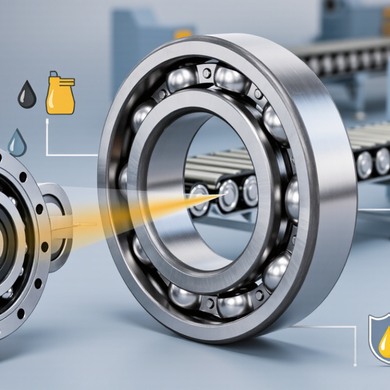
Lubrication deserves closer attention. Check oil viscosity, grease consistency, relubrication intervals, and contamination control. ASTM D3336 evaluates grease life under elevated temperature, offering useful comparison data, not a guaranteed service interval. Keep temperatures within the catalog range. Thermal expansion can reduce internal clearance and create damaging contact pressure. Seals also change the decision. Contact seals improve contamination resistance but may increase friction and heat. Open bearings can run faster, yet they demand cleaner housings.
Catalog limits are not suggestions. Compare the calculated speed with the limiting speed, then apply a safety margin for acceleration and duty cycles. ISO 15312:2018 explains reference conditions for bearing speed ratings, including lubrication and cooling assumptions. Those assumptions are easy to overlook. In field reviews, engineers often trust a single catalog number too quickly. That shortcut is tempting, but often wrong. Check shaft hardness, housing support, load direction, and misalignment. A bearing that survives laboratory testing may perform poorly beside dust, vibration, or intermittent starts. Recheck the selection after a temperature test. Small errors remain possible.
| Selection Checkpoint | What to Verify | Practical Engineering Data | Suitable Choice or Action | Important Catalog Limit |
|---|---|---|---|---|
| 1. Bearing Type | Available radial space, shaft arrangement, housing design, and whether an integral raceway is required. |
Drawn Cup
Thin outer shell; suitable for compact housings and generally used with a hardened shaft.
Machined Ring More rigid outer ring; suitable for higher loads, heavier shock, or grease retention requirements. Cage and Needle Assembly Very small radial section and low friction, but the shaft and housing must provide accurate raceways. |
Use a drawn-cup design for compact, economical applications. Use a machined-ring design when stiffness, load capacity, or sealing options are more important. | The selected design must match the required internal clearance, raceway hardness, shoulder geometry, and mounting method stated in the relevant catalog. |
| 2. Radial Load and Life | Applied radial load, shock load, duty cycle, required service life, and whether axial load is present. |
Needle roller bearings carry high radial loads relative to their radial cross-section. Basic rating life is commonly calculated from:
L10 = (C/P)10/3 for roller bearings, where C is the dynamic load rating and P is the equivalent dynamic bearing load. For variable loads, use an equivalent load based on the complete duty cycle. |
Select a bearing with sufficient dynamic capacity and confirm static safety for peak or shock loads. Use a thrust bearing or separate axial-load solution when axial forces are significant. | Do not compare load ratings between different bearing types without checking rating standards, internal geometry, lubrication, and mounting conditions. The catalog rating is not a guaranteed field life. |
| 3. Speed Capability | Rotational speed, direction of rotation, acceleration, load level, lubrication method, and operating temperature. |
Speed capability is commonly expressed as a limiting speed in revolutions per minute or by a speed factor such as:
Dm × n, where Dm is the mean bearing diameter in millimetres and n is speed in revolutions per minute. Grease lubrication generally permits a lower continuous speed than properly selected oil lubrication. Full-complement designs usually generate more friction than caged designs. |
Compare the required speed with the catalog limiting speed after applying load, lubrication, temperature, and sealing corrections. Reduce speed during run-in and after relubrication if the supplier specifies this. | A catalog limiting speed is not automatically a continuous operating speed. Verify permissible speed for the exact bearing series, clearance, lubricant, load, and seal configuration. |
| 4. Lubrication | Grease or oil method, relubrication interval, contamination level, speed, load, and compatibility with seals or surrounding materials. |
Grease
Simple and effective for many moderate-speed applications; helps retain lubricant and can provide some corrosion protection.
Oil Bath or Splash Useful for heat removal and continuous operation when oil level and churning losses are controlled. Oil-Air or Oil Mist Suitable for high-speed applications when a controlled, clean lubricant supply is available. |
Use a clean lubricant with the viscosity recommended for the load and operating temperature. Avoid mixing greases with different thickener systems or incompatible additives unless compatibility is confirmed. | Insufficient lubricant causes wear and overheating; excessive grease can also raise temperature and reduce speed capability. Follow the specified fill quantity and relubrication interval. |
| 5. Operating Temperature | Minimum and maximum temperature, temperature cycling, heat conducted from nearby components, and lubricant temperature limit. |
Standard bearing steel is often used in applications around -20°C to +120°C when the lubricant, seals, clearance, and load are suitable. Sealed arrangements commonly have a lower practical upper temperature limit, often near +100°C, depending on seal material.
Special heat-treatment or high-temperature materials may be required above these ranges. |
Choose the bearing, clearance, lubricant, and seal material as one system. Consider thermal expansion of the shaft and housing when operating temperature differs substantially from assembly temperature. | Never use a general temperature range as a substitute for the exact catalog rating. The lowest limit among the bearing material, seal, cage, grease, and surrounding components controls the assembly. |
| 6. Seals and Contamination | Presence of dust, water, metal particles, washdown, vacuum, chemical exposure, and available sealing space. |
Open
Lowest friction and easier heat dissipation, but requires a clean, protected environment.
Sealed Helps retain grease and exclude contaminants; increases friction and may reduce speed and temperature capability. Shielded Reduces entry of larger particles while generally producing less contact friction than a rubbing seal; it is not equivalent to a fully sealed arrangement. |
Use seals when contamination control and grease retention are more important than minimum friction. Provide external protection where water, abrasive particles, or pressure washing is expected. | Seal performance depends on shaft finish, shaft runout, misalignment, temperature, pressure, and chemical compatibility. A bearing seal is not a pressure seal unless specifically rated for that service. |
| 7. Shaft and Raceway Requirements | Shaft hardness, surface finish, roundness, runout, case depth, and whether the shaft or housing acts as the raceway. |
When no separate inner ring is used, the shaft normally functions as the inner raceway and must have suitable hardness and finish. A hardened and ground raceway is typically required for high load and long life.
A soft, rough, or poorly aligned shaft can reduce life even when the bearing itself has adequate load capacity. |
Use a separate inner ring when the shaft cannot provide the required raceway quality, when axial displacement is needed, or when sealing and mounting requirements make it preferable. | Use the fit classes, raceway dimensions, hardness, roughness, and geometric tolerances specified for the selected series. Do not assume that a standard shaft finish is adequate for every needle bearing. |
| 8. Internal Clearance and Fits | Shaft and housing tolerances, operating temperature, mounting interference, misalignment, and required running clearance. |
An interference fit can reduce internal radial clearance. Temperature differences between the shaft and housing can also change clearance during operation.
Excessive clearance may increase noise, vibration, and load concentration. Insufficient clearance may cause overheating, seizure, or premature fatigue. |
Calculate the assembled and operating clearance rather than selecting clearance only from the nominal bearing designation. Use the specified fit and clearance class for the exact application. | Press-fitting a bearing into an incorrect housing or over-tightening the shaft can distort the raceway. Confirm mounting forces and dimensional tolerances in the catalog. |
| 9. Misalignment and Mounting | Shaft deflection, housing distortion, angular misalignment, mounting method, and shoulder support. |
Needle roller bearings are primarily radial bearings and generally have limited tolerance for angular misalignment. Edge loading can occur when the shaft, housing, or raceways are not sufficiently aligned.
Pressing force should be applied only to the ring being fitted, or through a suitable installation tool when fitting a caged assembly. |
Improve housing and shaft alignment, use crowned or self-aligning components only when specifically permitted, and provide proper support at mounting shoulders. | Do not hammer directly on the rollers, cage, seal, or thin drawn cup. Incorrect installation can permanently deform the bearing or damage the raceway. |
| 10. Catalog and Dimensional Limits | Bore diameter, outside diameter, width, shoulder dimensions, chamfers, cage type, seal arrangement, and available clearance. |
The catalog drawing controls the actual limits for:
• Bore and outside diameter tolerances • Overall width and allowable housing depth • Shaft and housing shoulder diameters • Minimum fillet radius and chamfer requirements • Dynamic and static load ratings • Limiting speed and temperature |
Choose the exact part series only after checking the dimensional drawing, rating tables, installation instructions, and operating limits together. | Nominal dimensions alone are not sufficient for selection. A bearing that fits the bore and outside diameter may still fail because of inadequate shoulder clearance, incorrect raceway hardness, insufficient lubrication, or exceeded speed. |
| 11. Noise, Friction, and Efficiency | Required starting torque, running torque, vibration, acoustic noise, energy consumption, and temperature rise. | Friction generally increases with load, speed, lubricant viscosity, seal contact, misalignment, and excessive grease fill. Caged needle bearings usually have lower friction than full-complement designs under comparable conditions. | Use a caged arrangement for lower friction and higher speed where load capacity is adequate. Use a full-complement arrangement when maximum radial load capacity in a limited space is the priority. | Low friction and high load capacity involve trade-offs. Verify torque and temperature performance using the exact bearing, lubricant, seal, and operating conditions. |
| 12. Final Verification Before Release | Complete duty cycle, worst-case load, peak speed, minimum and maximum temperature, lubricant, contamination, fits, life calculation, and installation method. |
A suitable selection should pass all of the following checks:
Load: dynamic life and static safety Speed: catalog limit with application corrections Temperature: bearing, seal, cage, and lubricant limits Environment: contamination and chemical compatibility Geometry: dimensions, shoulders, fits, and clearance |
Record the exact bearing designation, revision of the technical catalog, lubricant specification, mounting tolerances, and acceptance limits in the engineering drawing or bill of materials. | Use the latest applicable manufacturer catalog and confirm the final selection with the bearing supplier when operating near any load, speed, temperature, life, or dimensional limit. |
Engineering note: The numerical ranges and formulas above are general screening guidance for needle roller bearing selection. Exact permissible speed, load rating, temperature, clearance, seal capability, and dimensional limits vary by bearing series and operating conditions; the current technical catalog for the selected series remains the controlling reference.